I have several EFUN SH331W smart outlets for controlling various lights. They’re based on a whitelabel ESP8266 design by Tuya, so I usually use tuya-convert to flash them with Tasmota so I can control them with MQTT. Unfortunately tuya-convert is a rather tedious and error-prone process, and recently I managed to soft-brick one.
Recovery for some devices is easy, you follow the normal Tasmota install instructions: Pop it open, connect TX, RX, GPIO0 to ground, GND, and 3.3v. When GPIO0 (aka pin IO0) is pulled down the ESP boots to flashing mode, and you can use esptool to flash tasmota directly.
Opening this device is less than straightforward — it’s a sealed plastic shell, and even with the most careful disassembly it would be pretty annoying to glue back together.
On the other hand, it would be a shame to have to toss a device that’s only soft-bricked…
Let’s use another one with bad flash memory1 to see what’s going on inside.
Investigatory Dissection
Or vivisection, I guess?
After a lot of careful cutting and prying around the edges of the unit, and a small blood sacrifice2, the innards were revealed. The ESP is its own module, sticking up from the main board, with all of the contacts we need hiding between the main board and the plastic back of the unit.
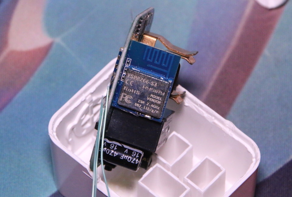
The module EFUN used is an ESP8266-S3 by Hysiry. We need access to pins 7 (IO0/GPIO0) to pull down for flashing mode, 11 and 12 (URXD/UART0_RXD, UTXD/UART0_TXD) for communication, and 13 and 14 (VCC/VDD, GND) for power. On many devices GPIO0 is connected to the external button, but the Tasmota template for this device shows it’s used by a status LED instead.
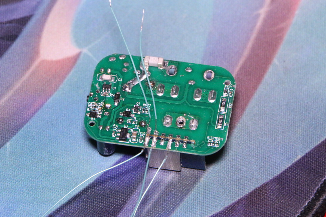
At this point I drilled five small holes in the plastic, expecting to stick
jumper wires through to touch the solder joints for the module. After spending
far too much time trying to hold all five in place with one hand while typing
picocom commands with the other, I gave up and desoldered the board from
the mains pins so I could add wires.
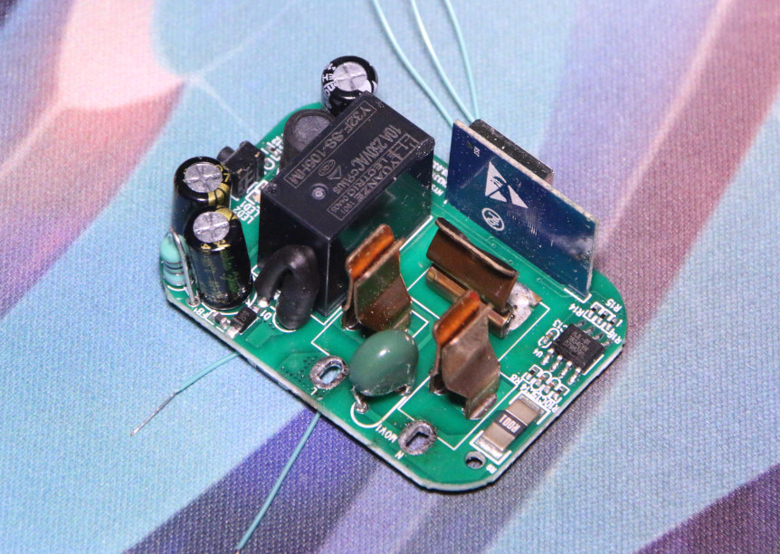
Now able to make a reliable physical connection, it was time to find several hundred ways not to communicate with it. To make a long story short, the bus pirate continues its legacy of technically working and being just helpful enough to not warrant replacing.
It seems the ESP, at least at this clock speed, uses a baudrate of 74880. This isn’t one the bus pirate offers, so I had to use the “BRG raw value” option.
BRG refers to the PIC Baud Rate Generator and the register used to configure
it. It’s described in section 17.1 of the
PIC24FJ64GA datasheet.
So for this bus pirate’s microcontroller, clock frequency, and firmware that
uses BRGH=1, brg=(4000000/baudrate)-1, so for 74880 baud we use a BRG of 52.
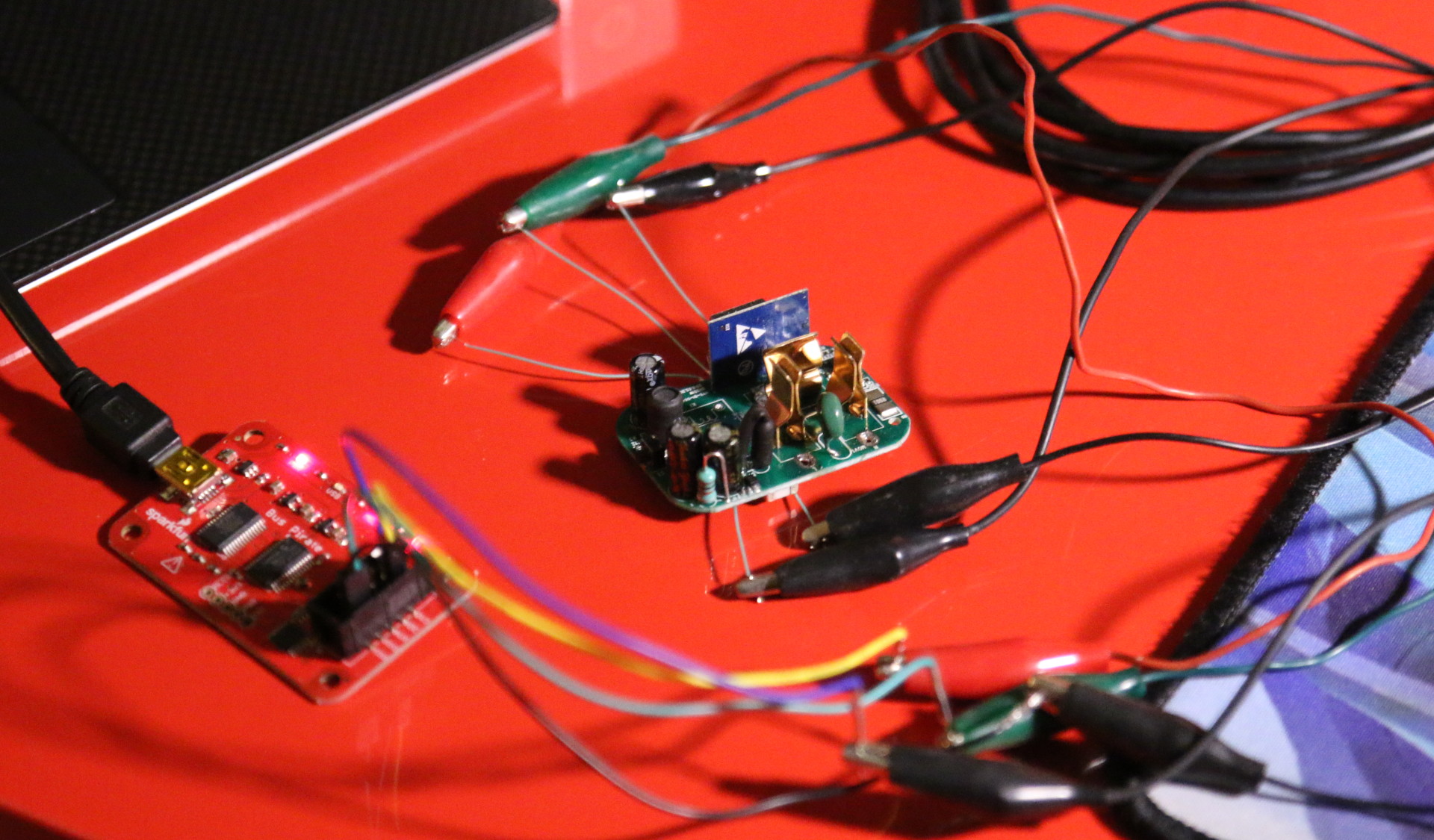
Connecting
For wiring, use the bus pirate’s GND to pin 7 and either pin 14 or the neutral prong, 3V3 to pin 13, MOSI to pin 11, and MISO to pin 12. Do not connect mains power.
The final incantation for the bus pirate:
$ picocom -b 115200 /dev/ttyUSB0
b to change host<->bp baudrate
10 for “BRG raw value”
52 for 74880 baud
Ctrl+a Ctrl+b 74880 to set picocom’s baudrate
m to change the bp<->device mode
2 for UART
10 for “BRG raw value”
52 for 74880 baud
Default data bits and parity, stop bits, and receive polarity (8N1, Idle 1)
2 for “Normal (H=3.3V, L=GND)” output
W to enable the power supply
(1) to start transparent bridge mode
You should then be able to see a bootloader message when removing and
replacing power for the device. You can exit picocom with Ctrl+a Ctrl+q.
With picocom closed, you can use esptool to communicate with the ESP.
- Test communication:
esptool -p /dev/ttyUSB0 --chip esp8266 -b 74880 read_mac - Flash tasmota (tasmota.bin from the releases page)
esptool -p /dev/ttyUSB0 --chip esp8266 -b 74880 write_flash -e -fs 1MB -fm dout 0x0 tasmota.bin
The Living Patient
It’s go time.
Now that I can directly flash the sacrificial device, it’s time to set up the one I hope to save.
Even knowing I was communicating with the ESP correctly, I wasn’t particularly excited about holding jumper wires in place. I realized I could reduce the number of wires I needed by one if I could connect to the mains neutral instead of the ESP’s ground contact, which worked. I also decided to use hot pins to poke through the plastic, since sufficiently precise pin placement would mean minimal manual holding.
The only ESP module information I could find gave exactly one relevant measurement, that the edge connector was 16.4mm. Calipers provided the rest3.
Based on these measurements, I needed pins at the following locations:
| pin | mm from plug end | mm from ground side |
|---|---|---|
| GPIO0 | 22.45 | 5.65 |
| UTXD | 27.50 | 7.90 |
| URXD | 27.50 | 5.65 |
| VCC | 30.02 | 5.65 |
Lastly, GND connects to neutral, the flat prong farther from the button.
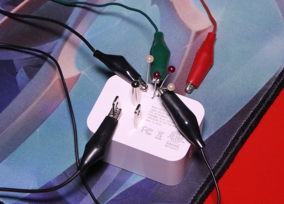
I measured with calipers, marked the grid with a knife, held each pin with pliers above a lighter to heat them until they glowed, and stuck them straight down at each location.4
One ended up a bit off-vertical, so I bent the pin in the other direction and reinserted it. Two more had plastic or soot on the tip, so those needed to be pulled, cleaned, and reinserted. Finally, with all the leads attached and gentle pressure on the pinheads…
ets Jan 8 2013,rst cause:1, boot mode:(1,0)
It lives! Disconnect picocom, run esptool, and…
Wrote 473856 bytes (328288 compressed) at 0x00000000 it 44.8 seconds (effective 84.6 kbit/s)...
Hash of data verified.
Pull the pins off, plug it in, and!

Conclusion
I spent several afternoons saving a $5 smart outlet. And then too long (in both words and time) writing it up, but I’m trying to document more stuff I do on the off chance some part of it ends up being useful to someone. Half the time that someone is just me, six months later.
This is probably also not the best idea from a standpoint of not lighting things on fire - it’s doing things that weren’t meant to be done to a device that controls up to 20 amps at 120 volts. Your device may also not be identical to mine. Attempting to follow these steps may break your smart outlet, make it burn your house down, or call your dog a bad girl, and I accept no responsibility for any of it.
-
It pretends to work fine, but forgets its settings about once a week. Useful for this, since I can test flashing but don’t feel bad about destroying it. ↩︎
-
If you don’t have the right tool handy, just go find it. ↩︎
-
1.25mm plastic wall above ledge, 3mm plug side board inset, 10mm from board edge to ESP module connector edge, 20.85mm from ESP module other end to other board end, 4mm button side board inset, 1.25mm wall. Sum of 56.75mm, measured size is 57mm - not bad. From the ground side, 1.25mm wall, 1.65mm board inset, module 2.75mm from board edge. ↩︎
-
No blood sacrifice was demanded at this step, but I still should have gone and dug out the pliers before the first mild burn. ↩︎
